Technology
REGULATORY BACKGROUND
The Environmental Protection Agency (EPA) has mandated that facilities producing, using, or transporting volatile organic compounds (VOC’s) must monitor their facilities for leaks. Most of these requirements are covered in federal publications 40 CFR, Parts 60, 61, 63, and 65.
The goal is to significantly reduce the amount of VOC’s entering the atmosphere from a wide variety of potential leak sources.
The techniques for monitoring these leaks are contained in EPA Method 21, which is also known as Leak Detection and Repair (LDAR) methodology. In broad terms, the EPA recognizes the distinction between detection and quantitative measurement of leaks.
Typically, a trained TVA operator can “sniff” about 500 components during an 8-hour work shift. Since a large petrochemical facility can have hundreds of thousands of components that need to be monitored for leaks, TVAs generally require a large commitment in manpower and maintenance expense for LDAR. The EPA recognized the shortcomings of this approach to leak detection, and amended Method 21 with an Alternative Work Practice (AWP) The Alternative Work Practice to Detect Leaks from Equipment can be found on the EPA Website under 40 CFR Parts 60, 63, and 65. This AWP provides the option of using Optical Gas Imaging in lieu of sniffers for gas leak detection.
Meets Sensitivity Standards with potential to detect gases leaking at just 0.4 g/hr, the device is verified to meet sensitivity Standard defined in the US EPA’s OOOOa methane rule.
PRINCIPLES OF IR IMAGING TECHNOLOGY
IR cameras have sensors that detect the difference in temperature between a target object or material and its surroundings (background). These sensors take the form of a focal plane array (FPA) of detector pixels. The camera lens focuses the infrared energy from a scene onto the FPA. The FPA output goes through a digital to analogy (D/A) converter and calibration electronics that produce a visible image of the scene on the camera’s display, including temperature data. Camera firmware allows the user to display the image as either a grey scale representation.
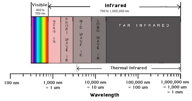
Detector materials are used to make an IR camera sensitive to specific portions of the IR spectrum, which covers a range of about 0.9µm to 14µm. For convenience, IR detector technology is described as Near IR (NIR), Mid wave IR (MWIR), or Longwave IR (LWIR). Cameras using these technologies may also use narrow band filters to be even more selective in the portion of the IR spectrum that is detected.
COMPOUND
UNITS
BENZENE
BUTANE
ETHANOL
ETHYL BENZENE
ETHANE
ETHYLENE
HEPTANE
HEXANE
ISO PRENE
METHANOL
3.5 Gms / hr
1.9 Gms / hr
0.7 Gms / hr
1.5 Gms / hr
0.6 Gms / hr
4.4 Gms / hr
1.8 Gms / hr
1.7 Gms / hr
8.1 Gms / hr
3.8 Gms / hr
COMPOUND
UNITS
MEK
MIBK
METHANE
OCTANE
PENTANE
1-PENTENE
PROPANE
PROPYLENE
TOLUENE
XYLENE
3.5 Gms / hr
2.1 Gms / hr
0.8 Gms / hr
1.2 Gms / hr
3.0 Gms / hr
5.6 Gms / hr
0.4 Gms / hr
2.1 Gms / hr
3.8 Gms / hr
1.9 Gms / hr
COMPOUND
I/min
Butane
Ethane
Ethylene
Methane
Propane
0.003
0.008
0.062
0.019
0.004
ADVANTAGES AND BENEFITS OF IR IMAGING
There are several advantages in the use of IR imaging technology for gas leak detection. The FPA and filter used in a camera can detect a broad spectrum of gases. The camera displays real-time video images that make gas leaks more obvious.
Individual video frames can be extracted as stills for use in reports. In addition, there are several practical advantages to IR imaging in maintenance operations. An IR camera can be used to scan a large area of plant real estate as a first step in gas leak detection. This greatly shortens the process of finding individual leaks compared to the use of sniffers. IR scans are also much safer in that they minimize the use of ladders and exposure of maintenance personnel to toxic gases. Nevertheless, they can easily trace a leak directly to its source, providing a visual confirmation of exactly where it originates. Moreover, that visual image is stored in camera memory, creating a record of the leak and its subsequent repair.
These advantages lead to a number of economic benefits for companies adopting IR imaging technology. First and foremost, it finds more leaks and finds them quicker to reduce product loss and the risk of fires and explosions. Similarly, it reduces the chance of getting an EPA citation for emitting VOC’s into the atmosphere. Because it’s safer than many other leak detection technologies, the risk of OSHA citations is also reduced.
When IR scans are incorporated into a predictive/preventative maintenance program, they make maintenance personnel more productive and lower costs. Reporting leak data along with Video report by help of in IR imaging technology can further increase its cost effectiveness.


